Category

BLDC Motor Supplier
Home » BLDC Motor Wiki » What is a Brushless DC Motor?
What is a Brushless DC Motor?
What is a BLDC Motor?
The electric motor with the mechanical commutation or the electronic commutation adheres to the same basic principle which transforms the electric energy into the mechanical energy. The current generates the magnetic field while passing the coil. Due to existence of the second magnetic field, the magnetic field (driven by the permanent magnetic iron) generates one force under the winding. When its conductor and the second magnetic field constitute an angle of 90°, the force reaches the maximum. To increase the number of coils can increase the output of the electric motor and the smooth electricity transmission.
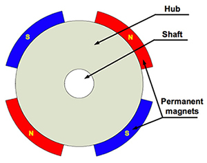
 By reversing the electric motor settings, the brushless DC motor overcomes requirements of the mechanical commutator. The winding becomes the stator, while the permanent magnet turns into a part of the rotor. The stator is usually made up of the steel plates. The axial-direction notching can include an even number of windings along its internal margin. The rotor is made up of one axis and one hub with the permanent magnet. The permanent magnet is aligned between two pairs to eight pairs of magnetic poles, and alternates between "N" and "S." Fig. 2 shows configurations of one commonly-seen magnetic iron. Under the condition, two magnetic irons can be directly connected to the rotor's hub.
 Fig. 2 :In the BLDC motor, the permanent magnet is attached to the rotor. The typical structures include alternation of two pairs to eight pairs of magnetic poles between N and S.
Since the winding is fixed, the permanent connection should be built for their electrification. In order to ensure the fixed winding to move the permanent magnet, the winding needs to be powered on or commutated to control the rotation magnetic field generated in sequence. Since the rotating magnetic field generated by the stator can rotate the rotor at the same frequency, the Brushless DC motor is known as "synchronous." The BLDC motor can be divided into the single-phase, two-phase or three-phase.
Basic principles of the BLDC motor
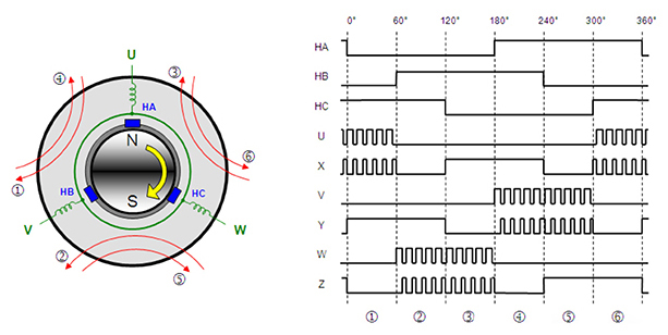
Through reverse of electric motor settings, the BLDC motor can get rid of the requirements on the mechanical commutator. The winding constitutes the stator and the permanent magnet forms a part of the rotor. The winding has its power supplied by the PWM-controlled six MOSFET bridges. Their commutation is based on the control sequence, and the rotating magnetic field is generated, thus dragging rotors revolving around it and driving the connected load.
 The Brushless DC motor uses the PWM signals for excitation of the windings one after another. The duty ratio of PWM signals is in proportion to the driving voltage. In this figure, "U," "V" and "W" are windings; "HA," "HB" and "HC" are position Hall sensors.
The commutation is decided by the relative position of the stator and the rotor, and measured by the Hall effect sensor, or through the range of the back electromotive force (limited to the sensorless electric motor).
Torque and speed characteristic figure
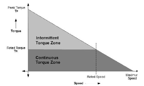
 The torque and speed characteristic figure demonstrates the torque and rotating speed characteristics. The BLDC motor follows two kinds of torque measurements: the maximum torque and the rated torque. When the electric motor operates continuously, it is reflected as a rated torque. Before the BLDC motor reaches the rated rotating speed, the torque remains unchanged, and the maximum rotating speed of the Brushless DC motor can reach 150% of the rated rotating speed. However, when it exceeds the speed, the electric motor's torque will decrease correspondingly. In the real-world applications, we usually have the electric motor with the load launched, stop rotation or operate in the reverse direction. At the moment, a torque which is larger than the rated torque is needed. Particularly, when the rotor is static and accelerates in the opposite direction, launch of the electric motor requires a larger torque to trade off the load and the inertial of the rotor itself. At the moment, the maximum torque should be provided until the electric motor moves into the forward-direction torque curve stage.
The electric motor with the mechanical commutation or the electronic commutation adheres to the same basic principle which transforms the electric energy into the mechanical energy. The current generates the magnetic field while passing the coil. Due to existence of the second magnetic field, the magnetic field (driven by the permanent magnetic iron) generates one force under the winding. When its conductor and the second magnetic field constitute an angle of 90°, the force reaches the maximum. To increase the number of coils can increase the output of the electric motor and the smooth electricity transmission.


Since the winding is fixed, the permanent connection should be built for their electrification. In order to ensure the fixed winding to move the permanent magnet, the winding needs to be powered on or commutated to control the rotation magnetic field generated in sequence. Since the rotating magnetic field generated by the stator can rotate the rotor at the same frequency, the Brushless DC motor is known as "synchronous." The BLDC motor can be divided into the single-phase, two-phase or three-phase.
Basic principles of the BLDC motor
Through reverse of electric motor settings, the BLDC motor can get rid of the requirements on the mechanical commutator. The winding constitutes the stator and the permanent magnet forms a part of the rotor. The winding has its power supplied by the PWM-controlled six MOSFET bridges. Their commutation is based on the control sequence, and the rotating magnetic field is generated, thus dragging rotors revolving around it and driving the connected load.

The commutation is decided by the relative position of the stator and the rotor, and measured by the Hall effect sensor, or through the range of the back electromotive force (limited to the sensorless electric motor).
Torque and speed characteristic figure

Post a Comment:
You may also like:

