Category

BLDC Motor Supplier
Home » BLDC Motor Wiki » Principle of Controlling Sensorless BLDC Motor with Back EMF
Principle of Controlling Sensorless BLDC Motor with Back EMF
BLDC control plan without the Hall sensor is similar to BLDC motor control plan with the Hall sensor, both of which make use of the "six-step commutation method". According to the current position of the rotor, stator winding is electrified according to certain sequence to make the BLDC motor rotate. The only difference is that sensorless BLDC motor requires no Hall sensor. Through detection of the back electromotive force zero-crossing-point of the stator winding, the current position of the stator can be judged. Compared with the control plan with the Hall sensor, the most striking advantage of sensorless BLDC motor control plan is that it reduces cost and volume. Meanwhile, the motor leads change from eight pieces to three pieces, which largely simplifies the wiring debugging. Meanwhile, the Hall sensor is subject to influence of the external environmental factors, including temperature and magnetic field. This can well explain the high fault rate of the Hall sensor and the growing applications of BLDC without the Hall sensor. In fact, sensorless BLDC motor is replacing BLDC motor with the Hall sensor under many conditions.
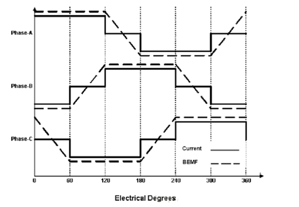
When the BLDC motor is rotating, rotation of the permanent magnetic rotor can generate the changing magnetic field within the motor. According to the law of electromagnetic induction, every phase of winding can perceive the back electromotive force. The BEMF waveform of BLDC motor changes along with the rotor position and speed, and is in a trapezoid shape on the whole. Fig. 1 presents the waveform of the current and back electromotive force for the BLDC motor which rotates for one electrification period, where the solid line denotes the current, the imaginary line represents the back electromotive force, and the horizontal coordinate represents the electric perspective of motor rotation. According to "six-step commutation" control theory of BLDC, it can be seen that the three-phase BLDC motor just has two-phase electrification with the third phase being at the open circuit. Each two phases among the three phases are connected to form six combinations and combinations are changed at certain sequence and by 60° each time. The magnetic field generated by rotation can pull the permanent magnet to move along with it. Here, 60° refers to the electric perspective. One electricity cycle is not absolutely corresponding to a complete mechanical rotation cycle of the stator. The number of electricity cycles to be repeated by accomplishment of one circle of mechanical rotation depends on the number of pole pairs of the rotor. Every pair of rotor magnetic poles should finish one electricity circle. Therefore, dividing the number of rotations by the number of electricity cycles can obtain the number of pole pairs of the rotor.

As one observes in Fig. 1, the zero-crossing point of back electromotive force occurs at the phase without electrification. For example, within the first 60° of Fig.1, A-phase current is positive, B-phase current is negative, and C-phase current is zero. This means that the motor A and B are connected, meaning that the current flows from A-phase to B-phase, and C-phase features an open circuit. The zero-crossing-point of back electromotive force exactly appears at C-phase. Meanwhile, since C-phase is not connected with power, it has no current. The phase voltage and the back electromotive force are directly corresponding to each other. Therefore, as long as the voltage of the phase without electrification is detected in every 60°, the back electromotive force can be detected.

Fig.1 BLCD motor current and back electromotive force waveform
The linchpin to BLDC control is identification of the phase-switching moment. From Fig. 1, it can be seen that the middle of every two phase-switching points is corresponding to one point whose back electromotive force polarity is changed. For example, the point in which the back electromotive force changes from positive to negative or from negative to positive is called the zero-crossing-point. Based on the characteristic of the back electromotive force, as long as we can correctly detect the zero-crossing-point of the back electromotive force, we can identify the phase-switching moment by delaying the point by 30°.As one observes in Fig. 1, the zero-crossing point of back electromotive force occurs at the phase without electrification. For example, within the first 60° of Fig.1, A-phase current is positive, B-phase current is negative, and C-phase current is zero. This means that the motor A and B are connected, meaning that the current flows from A-phase to B-phase, and C-phase features an open circuit. The zero-crossing-point of back electromotive force exactly appears at C-phase. Meanwhile, since C-phase is not connected with power, it has no current. The phase voltage and the back electromotive force are directly corresponding to each other. Therefore, as long as the voltage of the phase without electrification is detected in every 60°, the back electromotive force can be detected.
Post a Comment:
You may also like:

