Category

BLDC Motor Supplier
Home » BLDC Motor Application » FOC Technology of BLDC Motor for UAV
FOC Technology of BLDC Motor for UAV
Brushless DC (BLDC) motors are widely used in the design of hard disk drives, cooling fans, DVD players and other electronic devices because of their long life, dc power supply and relatively affordable. Normally, the speed and torque of BLDC motor are controlled by MCU using scalar technology.
Now a new type of application is emerging quietly, among which the four-rotor UAV is the most representative, and this kind of application is increasingly favored by amateurs. Drones are also being considered for commercial applications such as surveillance. Of particular importance to these applications is the dynamic response of the BLDC motor controller and its ability to smoothly control the BLDC motor at low speeds and without sensors.

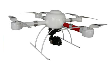
Fig.1 Four rotor UAV
Scalar techniques are not precise enough for dynamic load change applications. Magnetic field directional control (FOC) technology can greatly improve the accuracy, so it is widely used to drive high-end industrial AC equipment. By implementing FOC, BLDC motor can provide accurate control over drones and other high-performance applications (such as medical robots, universal systems, and autonomous driving vehicles) at reasonable cost.
Field-oriented Control (FOC)
The traditional scalar technology used to control the high speed micro BLDC motor is known as the six-step (trapezoid) control. The stator will be driven by the six-step process to generate vibrations on the torque. Every pair of winding is connected with power until the rotor arrives at the next position. At the moment, the electric motor will switch to the next step. As to sensorless applications, the back electromotive force generated by the stator winding is usually used to identify the position of the rotor.
The dynamic response of the scalar control cannot process rapid changes of the dynamic load. Therefore, the vector control is gaining wider and wider applications, ranging from white household appliances (such as washing machines) driven by the AC electric motor to products powered by batteries.
As one of the most commonly-used methods for vector control, FOC follows the following working principle: manage the stator winding to ensure the flux generated by the rotor's permanent magnet to be orthogonal to the stator's magnetic field.
FOC is first developed to control the three-phase AC electric motor. Considering that the small-scale UAV's BLDC motor is a 21V battery (five-joint lithium polymer battery), the electric components must include the low-voltage three-phase inverter system. The other major electric components include the electric motor driver, MCU and software implementing the FOC algorithm. Among them, the software is the most important.
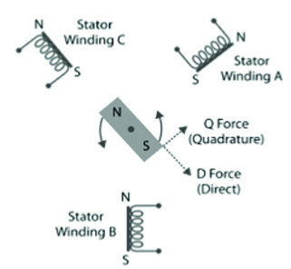
FOC processing is accomplished within the direct-axis—quadrature-axis (d-q) domain or a rotation reference system. The direct-axis and the quadrature-axis are two components decomposed by the flux linkage vector, namely the flux (d) and the torque (q). The relationship can be presented in Fig. 2. The current within the electric motor's stator winding is under a controlled status, which can ensure the flux generated by the rotor's permanent magnet to be orthogonal (90°) to the stator's magnetic field. Apart from achieving accurate electric motor control, this method can also provide an accurate torque control. This is also the operating advantage of this method in the d-q coordinate system.

Fig.2 d-q torque component
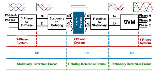
The FOC includes three domain conversions:
1. The phase current measured in the stator converts from the three-phase static coordinate system to the two-phase static coordinate system (α, β).
2. The two-phase static coordinate system converts into the rotation binomial coordinate system (d-q) aligned with the rotor flux.
3. In order to effectively actuate the electric motor, the d-q component returns to the stator coordinate system and applies it to the spatial vector pulse width modulation (SVPWM). The whole process is shown in Fig. 3.

Fig.3 FOC control domain transformations required
Now a new type of application is emerging quietly, among which the four-rotor UAV is the most representative, and this kind of application is increasingly favored by amateurs. Drones are also being considered for commercial applications such as surveillance. Of particular importance to these applications is the dynamic response of the BLDC motor controller and its ability to smoothly control the BLDC motor at low speeds and without sensors.

Fig.1 Four rotor UAV
Field-oriented Control (FOC)
The traditional scalar technology used to control the high speed micro BLDC motor is known as the six-step (trapezoid) control. The stator will be driven by the six-step process to generate vibrations on the torque. Every pair of winding is connected with power until the rotor arrives at the next position. At the moment, the electric motor will switch to the next step. As to sensorless applications, the back electromotive force generated by the stator winding is usually used to identify the position of the rotor.
The dynamic response of the scalar control cannot process rapid changes of the dynamic load. Therefore, the vector control is gaining wider and wider applications, ranging from white household appliances (such as washing machines) driven by the AC electric motor to products powered by batteries.
As one of the most commonly-used methods for vector control, FOC follows the following working principle: manage the stator winding to ensure the flux generated by the rotor's permanent magnet to be orthogonal to the stator's magnetic field.
FOC is first developed to control the three-phase AC electric motor. Considering that the small-scale UAV's BLDC motor is a 21V battery (five-joint lithium polymer battery), the electric components must include the low-voltage three-phase inverter system. The other major electric components include the electric motor driver, MCU and software implementing the FOC algorithm. Among them, the software is the most important.
FOC processing is accomplished within the direct-axis—quadrature-axis (d-q) domain or a rotation reference system. The direct-axis and the quadrature-axis are two components decomposed by the flux linkage vector, namely the flux (d) and the torque (q). The relationship can be presented in Fig. 2. The current within the electric motor's stator winding is under a controlled status, which can ensure the flux generated by the rotor's permanent magnet to be orthogonal (90°) to the stator's magnetic field. Apart from achieving accurate electric motor control, this method can also provide an accurate torque control. This is also the operating advantage of this method in the d-q coordinate system.

Fig.2 d-q torque component
1. The phase current measured in the stator converts from the three-phase static coordinate system to the two-phase static coordinate system (α, β).
2. The two-phase static coordinate system converts into the rotation binomial coordinate system (d-q) aligned with the rotor flux.
3. In order to effectively actuate the electric motor, the d-q component returns to the stator coordinate system and applies it to the spatial vector pulse width modulation (SVPWM). The whole process is shown in Fig. 3.

Fig.3 FOC control domain transformations required
Post a Comment:
You may also like:

